
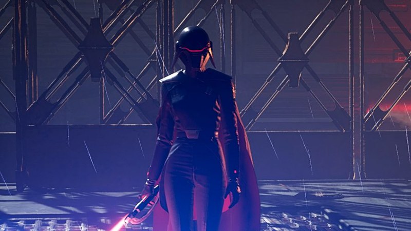
This is the Second Sister from the video game Jedi: Fallen Order. An Imperial Inquisitor on a mission to hunt down the remaining Jedi sometime between Order 66 and the beginning of A New Hope, I've been stalled out playing the game because I'm a terrible gamer and can't fight my way past her. So I only play for a few minutes a week when I feel like getting beaten and abused by a woman dressed in black and knee-high boots.
But that's an issue for another time...
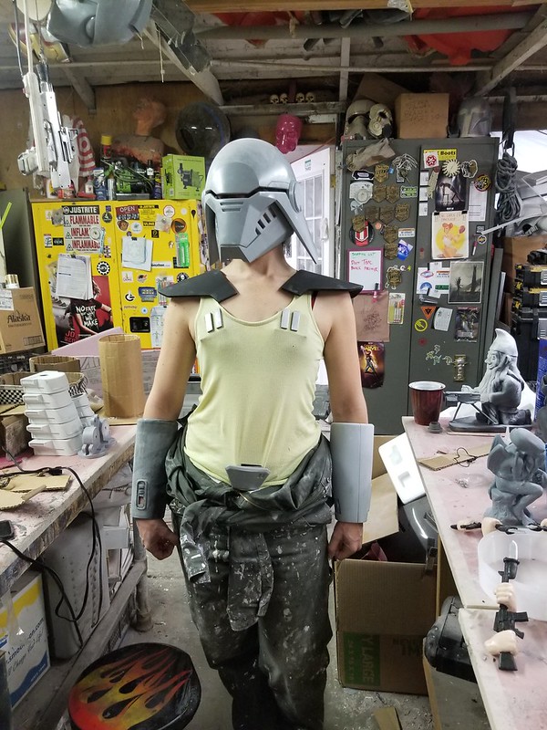
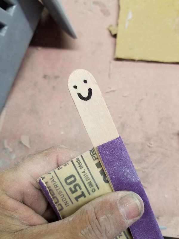
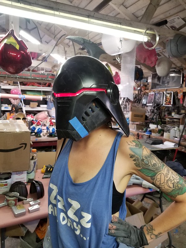
I didn't end up writing in much detail about the actual trimming and prep work. Mostly because it's not very interesting, but also because I tend to forget to take pictures during the process. Largely because I look like this:


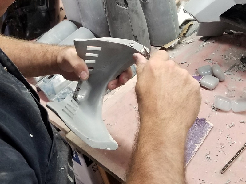
Fine tuning the edges was done with a medium grit (probably 120, but I don't pay attention) sanding drum. Like this one:


Lighting the Visor
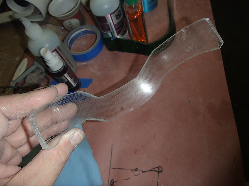
I started by cutting out a piece of 1/4" acrylic sheet and heating it up until I could bend it into place inside the helmet. Then I used a hacksaw blade to scratch a quick and dirty crosshatching pattern into the inner surface:
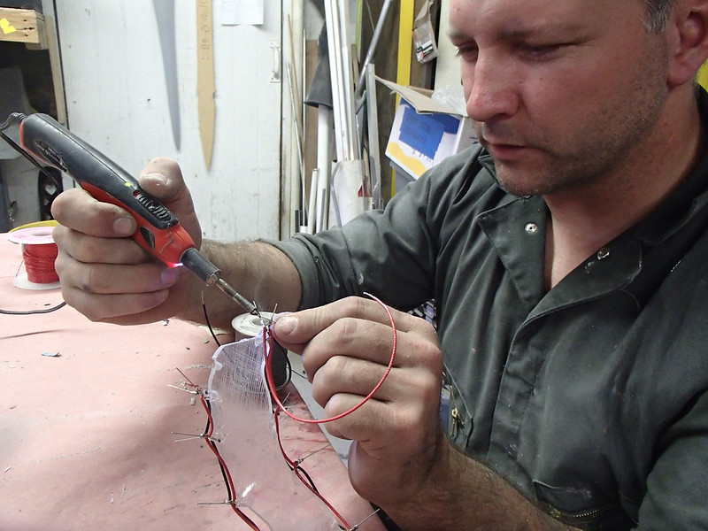
Then I soldered up an LED array that was glued into place to edge-light the sheet:
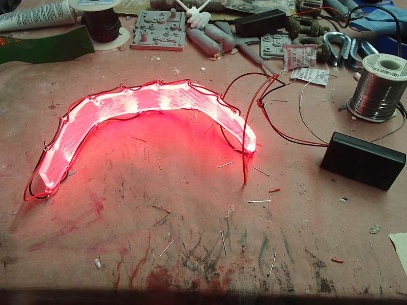
When it was powered up, the scratched lines picked up the light pretty well:
As you might expect, this is a lot of light inside the helmet and makes visibility hard for the wearer:

To make sure she wouldn't be blinded by the light, revved up like a deuce, another runner in the night...
Here's an initial test fitting with the lights in place:
My assistant Rachel spent a few minutes walking around the shop and managed to avoid knocking into anything (or at least no more than she'd usually stumble into) so it seemed like it would work out:


The main disappointment was that the rough scratches from the hacksaw blade made for an uneven light distribution and blurry spots in the wearer's vision. To make up for this, I hit up my friend Jesse at Puzzlebox Props for some time on his laser cutter. He made me some much nicer clear acrylic pieces with this very uniform crosshatching pattern etched into the surface: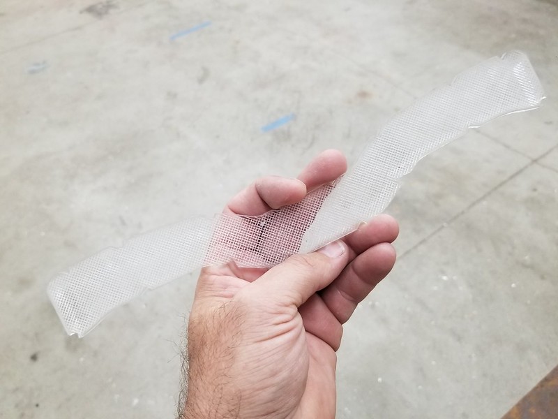
To get these pieces to fit into the helmet, they were placed in a toaster oven for a few minutes until they were warm enough to flop into place in the helmet:

It's important to pay attention during the heating process. Cooking them for just a bit too long will cause acrylic pieces to bubble up and become completely useless. So you have to watch it pretty close and check from time to time to see if it's flexible enough to force into place. It's not a very interesting show:

But as soon as it gets warm enough to form, I lay it in place inside the helmet and it's left to cool:

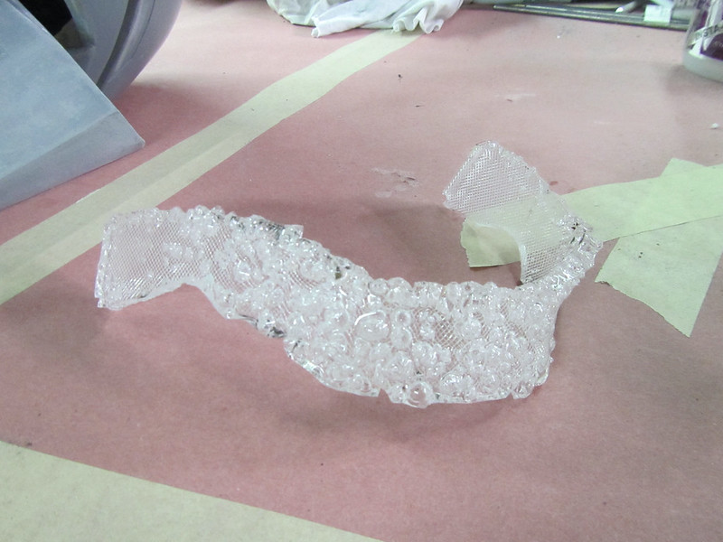
That's what it looks like when it's formed in time. If it's overcooked, it turns into this hot mess:
Once the parts were formed other refinement was to notch the bottom edge with a sanding drum so it would fit a bit better where the cheekbone area was inside the helmet:
With all of the forming and trimming done, it was time to round up the necessary tools for the lighting:

The wire strippers are one of the handiest things I've bought for my limited electronics work. Next to them is a pair of wire cutters for speedy cutting of wires and nipping off the ends of the LED leads. Needle-nosed pliers turn out to be useful for undoing the occasional screwup in the assembly phase. The soldering iron is for soldering the connections together and the hot glue gun lets me do a quick and dirty version of covering any exposed elements and potting the wiring so I don't have to worry about something getting bumped and causing a short later.
Before soldering any LEDs into place, I made it a point to mock up a breadboard circuit first. I also have a handy LED tester that lets me check each of the LEDs before I inadvertently wire in a burnt-out one that missed the trash can: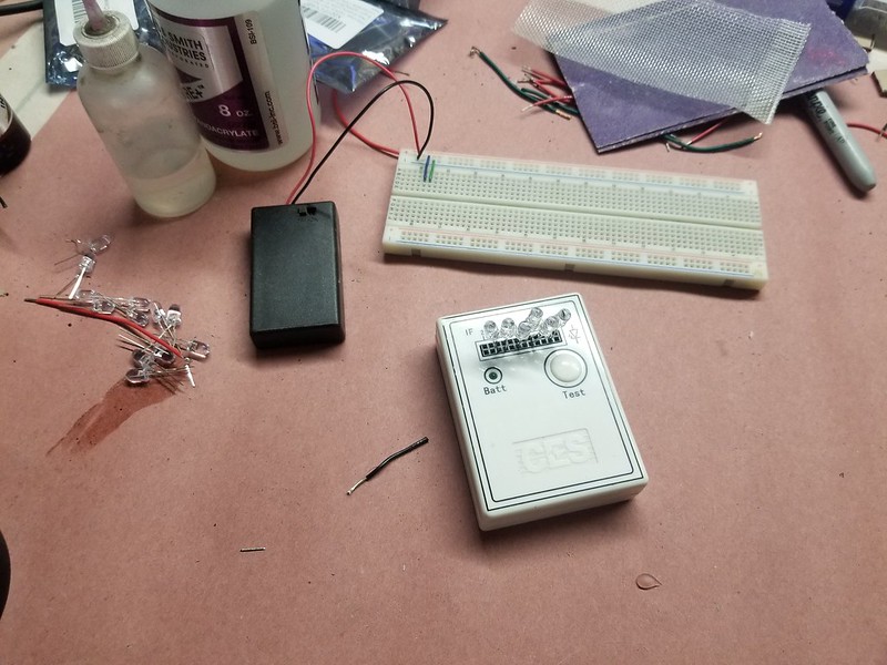
With a couple of bags of LEDs, spools of hook-up wire, and a stack of battery boxes at the ready, it was time to get started. Here's what the breadboard mockup circuit looked like:
What you're looking at is sixteen LEDs wired up in eight parallel sets of pairs in series. If you're the kind of nerd that needs a circuit diagram instead, it looks like so:

Stretched out for clarity, the soldered version looks like so:

With the lighted circuit all wired up and tested, the LED were glued into the notches on the acrylic visor with a few drops of CA glue:
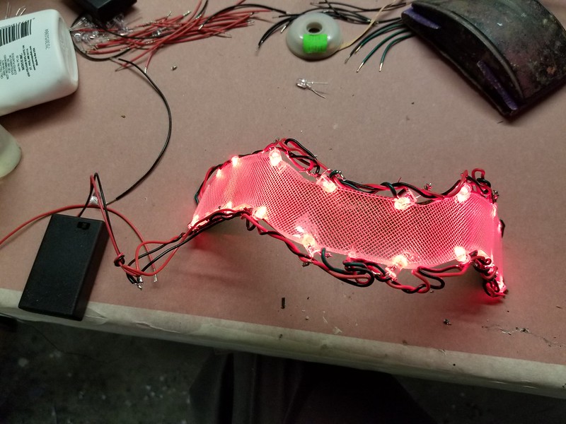
Someone out there is going to ask why I don't have any resistors in the circuit to protect the LEDs. I'd like to say that I did all the math and it turns out that with the voltage drop across each diode the serial pairs are able to handle the current without any problem. The real truth of it is that after my initial breadboard test with all sixteen LEDs in parallel just made sixteen neat little popping noises and corresponding puffs of smoke, I just kept trying different layouts until I was able to get the whole thing as bright as possible without letting any of the magic electron smoke out of the wires. This version of the LED array stayed lit for seven straight hours without dimming or burning out any LEDS, so I'm confident it'll work just fine.
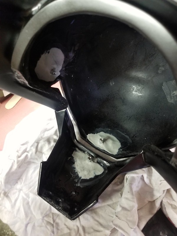
To install them in the helmet, I needed an option that would make them removable later in case anything ever goes wrong with the wiring. So I started by gluing in a series of T-nuts so I could just bolt them in:

Later I refined the plan to use four T-nuts instead of three. Once they were glue in, I used Magic Sculpt epoxy putty to reinforce their attachment points:
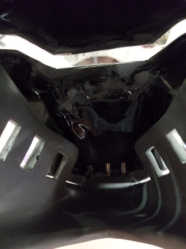
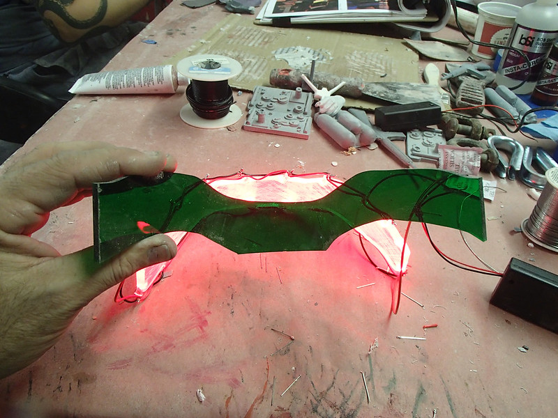
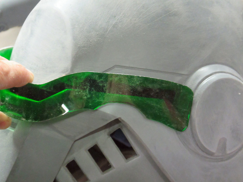
With the lighted visor and interior green tinted layer in place, it looked like so:

The remaining light leaking in around the edges was blocked out with judicious application of gaffer's tape after everything was painted: 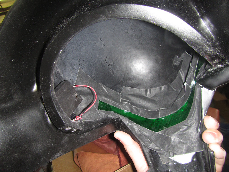
But I'm jumping ahead...
Lighting the Forearms
For the little lights in the bracers, I had an even simpler approach. Since space was at a premium, I couldn't put in very big batteries. After an exhaustive research and development process, I determined that the optimal circuit would use two CR2032 button cell batteries and a single high-intensity LED. Actually, that's not true. In reality, I had a bunch of these handy two-cell battery holders wired up with built-in switches on hand and it was really easy to attach a single LED and glue it to the end of a piece of red-tinted acrylic to make the light I needed:
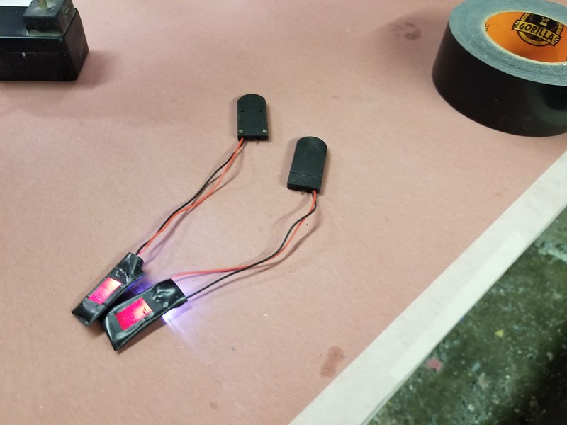
Once the painting was done, they'd fit nicely into the square hole on the bracers. Gaffer's tape contains any light leaks on the inside and a patch of velcro would keep the battery pack from rattling around.
The end result looked like so:

Again, I'm jumping ahead.
Painting and Final Details
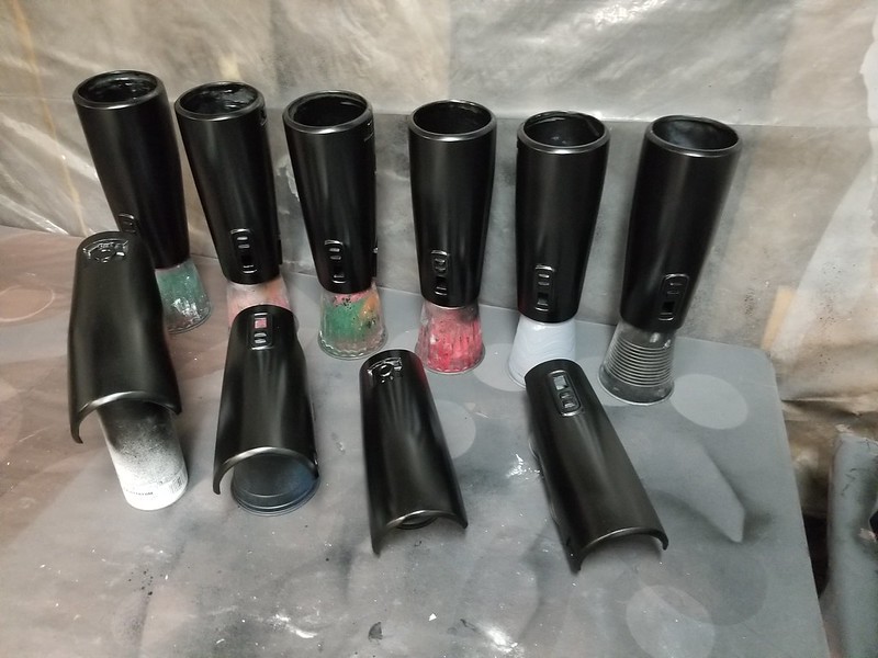
When it comes to prop and costume making, the biggest problem I have is that I almost never make just one of anything. This same thing held true here. The helmets were trimmed and prepped and primed and given several coats of satin black:

The bracers too:
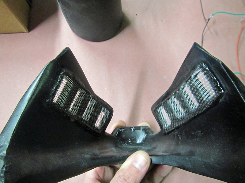
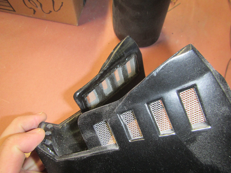
With the painting finished, the final touch was to add a bit of metal screen door mesh to the holes in the cheek vents:
So with all that said and done, here's the Lady Shawnon trying on the parts all finished and waiting on the soft parts of the costume to be sewn up:

Stay tuned...
Mr. Mixing Stick is my new favorite.
ReplyDelete