I replied that I could, but I'd need a lot more information. How large is large? Where is it going outdoors? What kind of budget do I have to work with? That sort of thing.
We ended up having a brief phone conversation before I was introduced to Joel Jones of Basal Ganglia Studios, who presented me with this concept sketch:
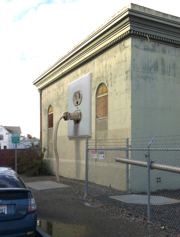
That's a Photoshopped image of an historical building downtown next to an electrical power substation. Basal Ganglia had been funded to add a sculptural installation to the side of the building. My role: fabricate a giant rendition of a household electrical outlet with a cord plugged into it and leading into the ground.
No problem.
I had a few other projects in my queue ahead of this one, but once I'd started, it took a few weeks, a whole lot of fiberglass, and a few hundred pounds of steel to end up with this:
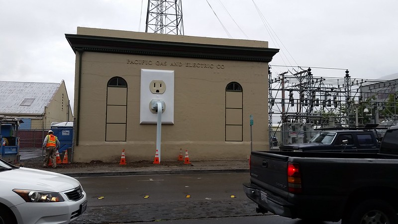
For more details and photos of how it was made, read on...
The very first thing to do was determine the scale of the thing. Joel finally settled on making the cover plate ten feet and six inches tall. At that scale, it would mean making it six feet and five inches wide. The first challenge was finding enough floor space to lay the whole thing down:
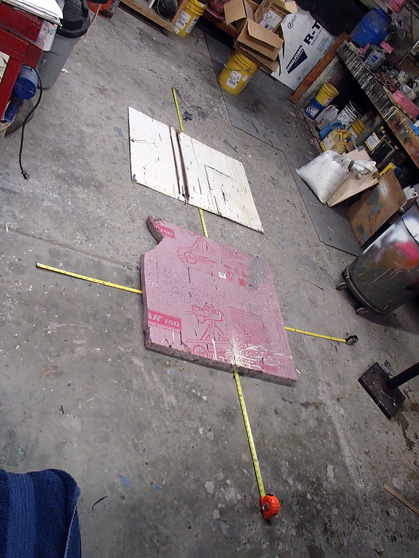
Once I was sure the project would actually fit in the shop, I got to work. I began with...
The Receptacles:
Since the standard electrical outlet has two matching receptacles, I decided to make a prototype and then mold it to create two fiberglass copies. The prototype began with me drawing it out on a piece of two-inch thick insulation foam:
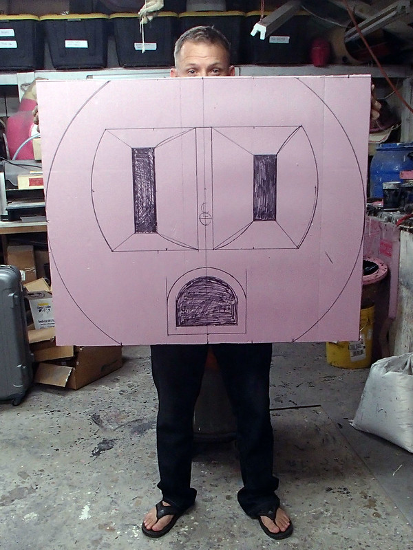
It's not small.
Once I was happy that I'd transferred all of the necessary dimensions to the piece of foam, I cut out the outline and carved in the details with rasps, saw blades, knives, and sandpaper. It came out pretty good:
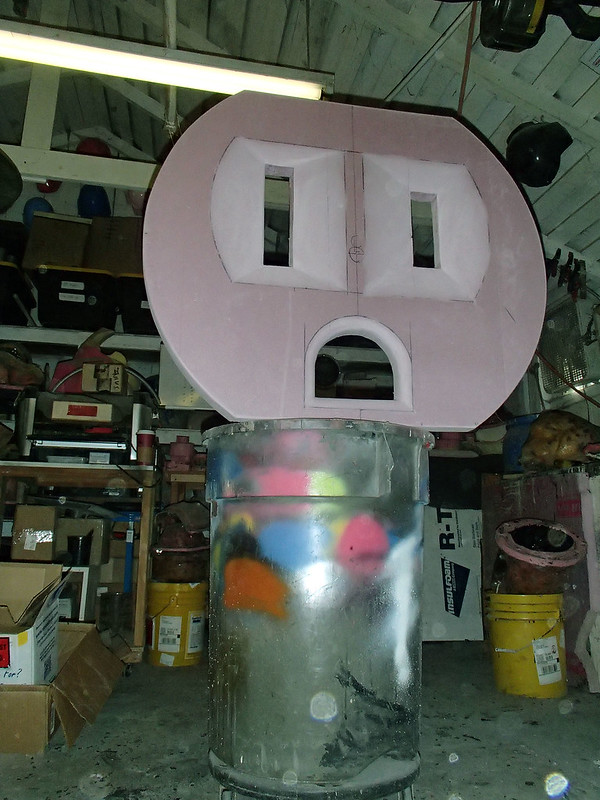
After skinning over the foam with urethane resin, the whole thing was smoothed out using automotive body filler and given a coat of gloss lightish red paint in order to make it as smooth as possible:
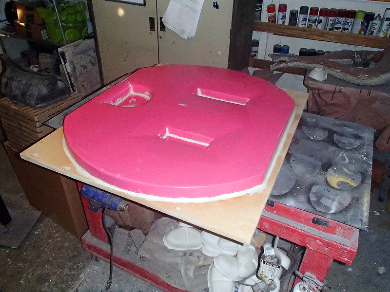
After applying a release agent, I coated the whole thing with orange tooling gelcoat and laid up the fiberglass mold.
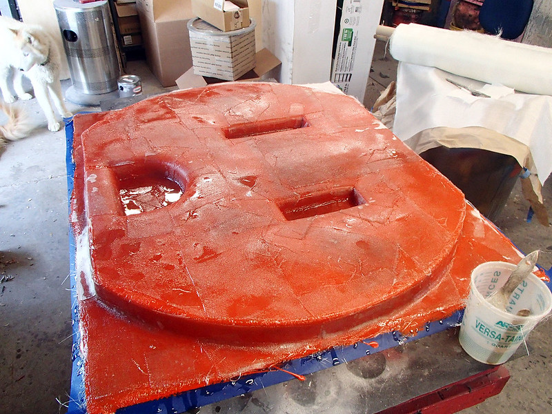
In order to keep everything straight and flat, the mold was reinforced with wooden battens:
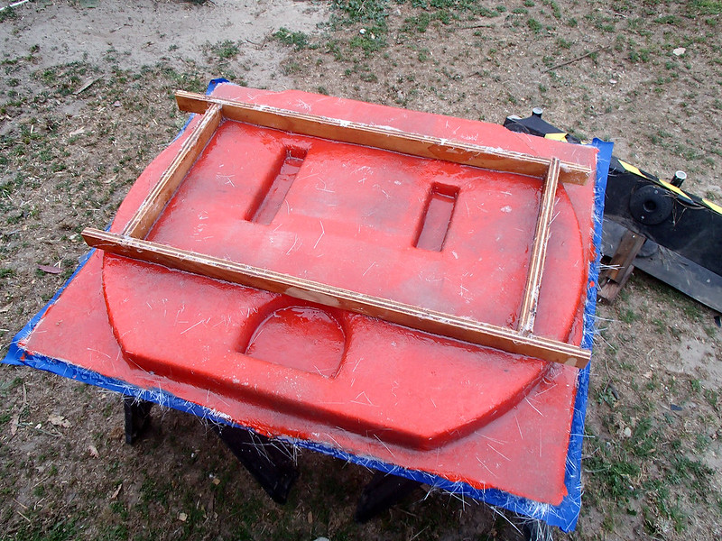
Once the fiberglass had set up, the next step was to remove the prototype. Being made out of some pretty flimsy stuff, this meant destroying it in the process:
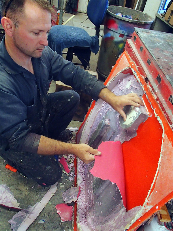
Fortunately the mold came out pretty clean when it was all picked out:
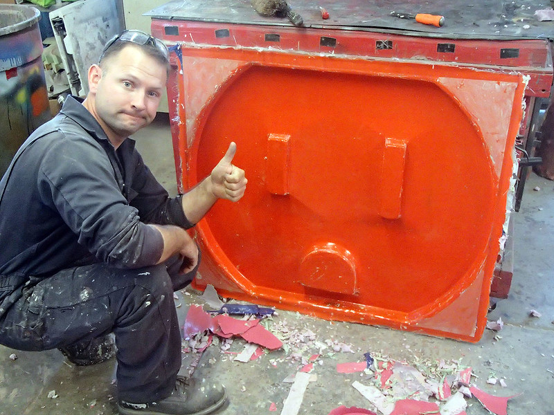
After a bit of touchup, the mold was polished and coated with a release agent:
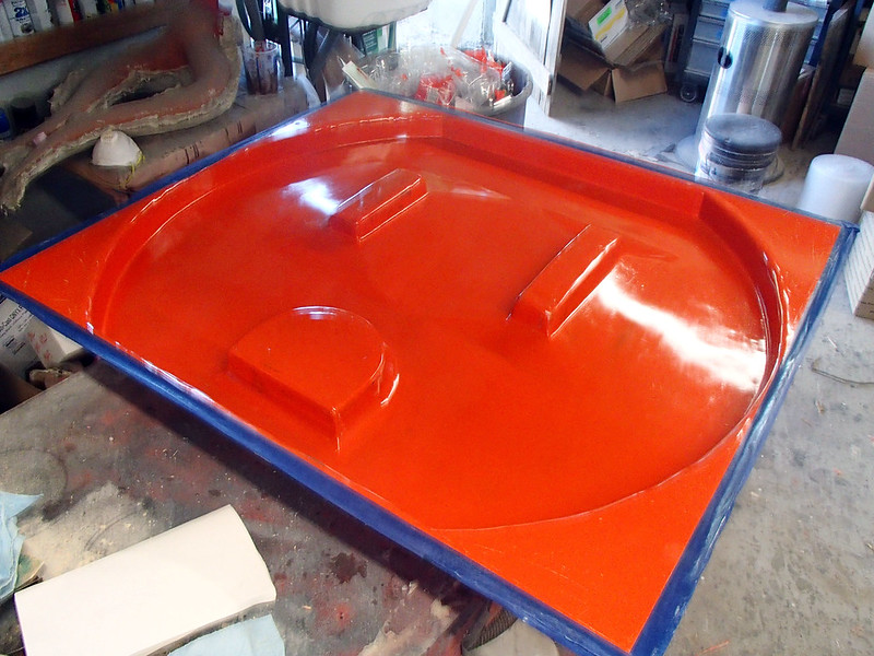
Then gelcoat:
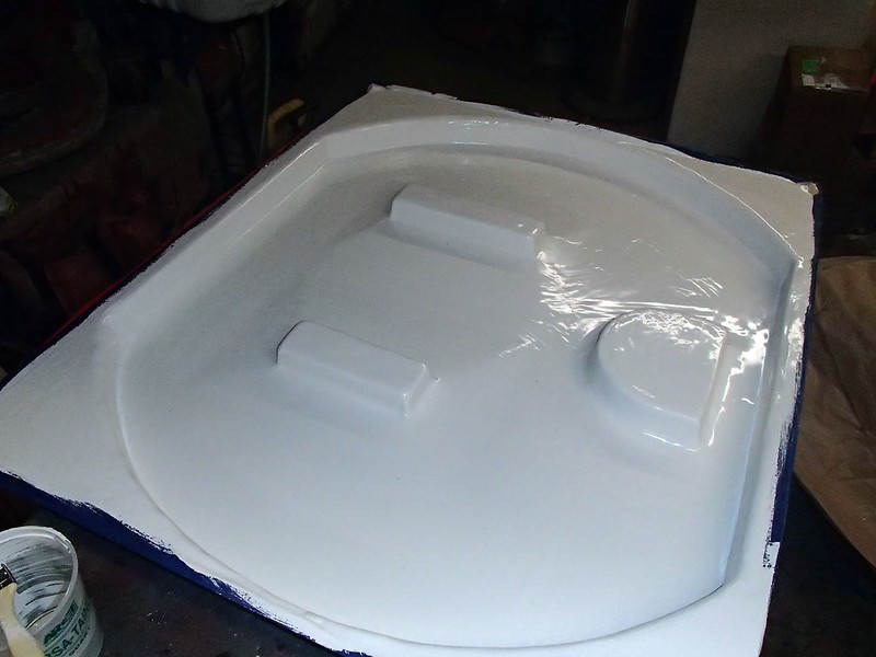
Then I laid up the fiberglass:
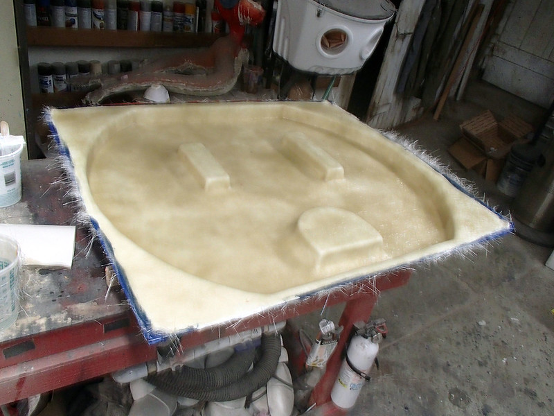
The first copy popped out of the mold pretty neatly:
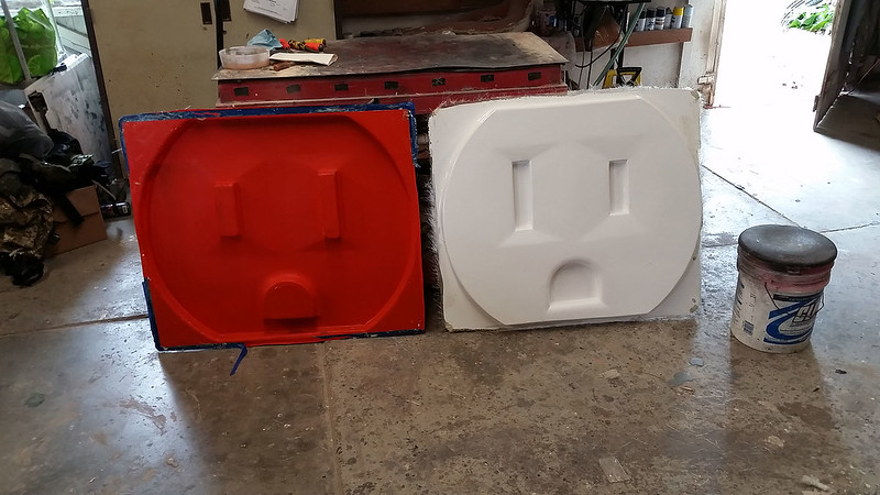
So did the second one:
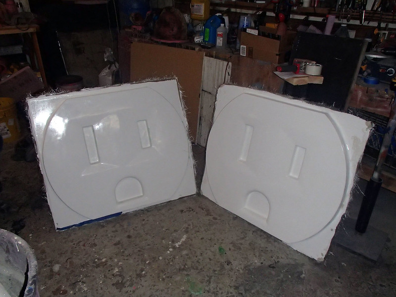
Here they are all trimmed and painted and set outside:
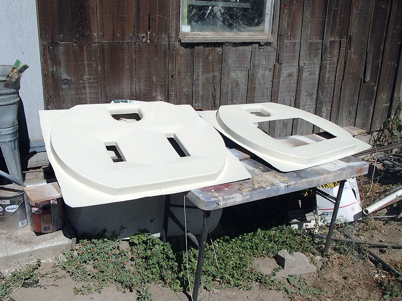
This will make more sense shortly.
With the first couple of little parts done, it was time to move on to the big part.
The Cover Plate:
The first step in making the cover plate was to make the mold. Normally I would start a project like this by making a prototype and then pulling the mold off of that, but since we would only ever make one of these pieces, I settled on making a single-use, disposable mold instead. This meant that I would have to make an inside-out version of the shape that I wanted.
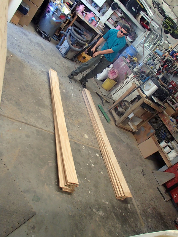
I started by clearing a bunch of space in the shop and my friend Trevor gave me a hand ripping down some lengths of 1/2" shop plywood:
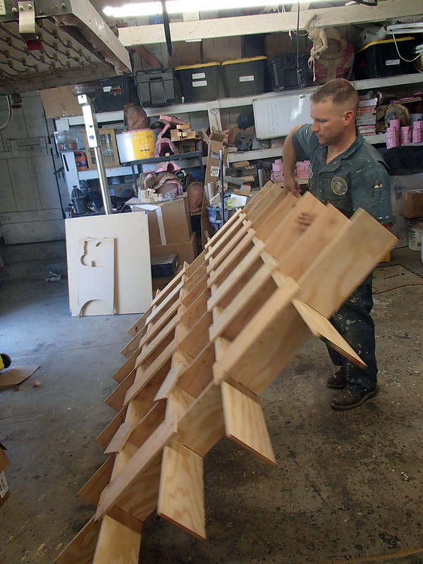
The strips of plywood were slotted so I could fit them together into this giant egg crate assembly:
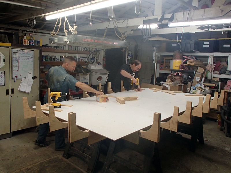
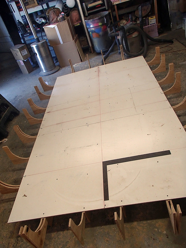
Frames were added around the edges to create the curved edge profile and then my friend Matt and I skinned over the flat area in the middle of the mold with 1/4" melamine sheet:
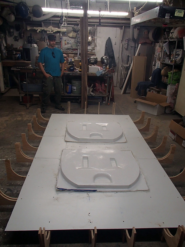
A quick test-fitting of the receptacles was done to ensure that the proportions still looked right:
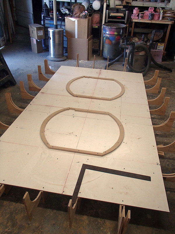
In order to make the holes that the receptacles would fit through, I laid out a series of measurements:
The outlines of the cutouts were made out of some scraps of 3/4" MDF:
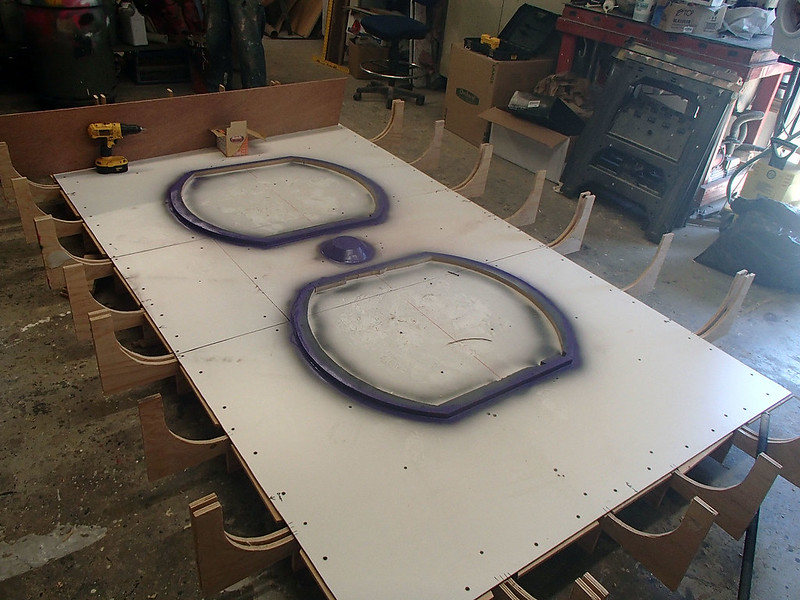
I also made the recess for the countersunk screw head that would go into the middle of the plate, then gave everything a few coats of gloss plurple spray paint in order to smooth it all out:
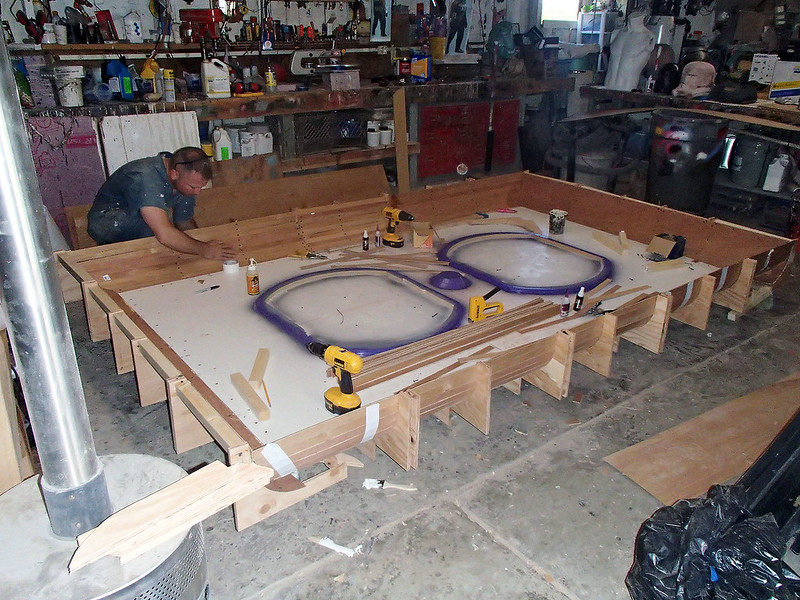
At this point, it was time to create the curved edges of the plate. I started by bending some 1/8" luan plywood into the curved frame sections around the edges. For the longer sides, I opted to use thin strips of ply instead of trying to fight the full-width pieces into the curve.
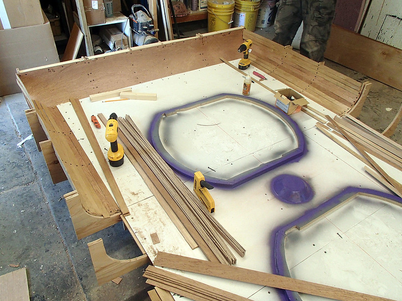
All of these pieces were glued and screwed into place:
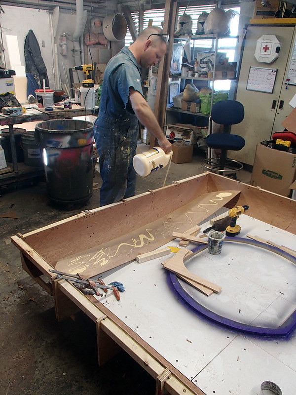
The next day I added another layer of 1/8" luan ply on top of the curved sections that were in place. This process started with cutting the shapes that I needed, buttering them up with wood glue, then forcing them into the curved profile they'd need. These pieces were held in place with drywall screws while the glue set up. Here I am adding the wood glue to the backside of one of the longer pieces:
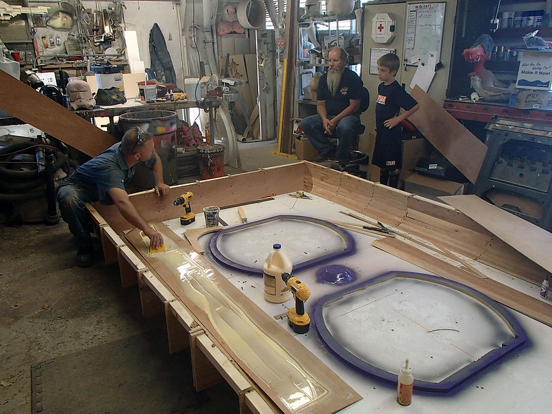
Once the second layer was built into the long side, I checked to make sure I hadn't knocked anything out of alignment. As luck would have it, everything was still straight and square:
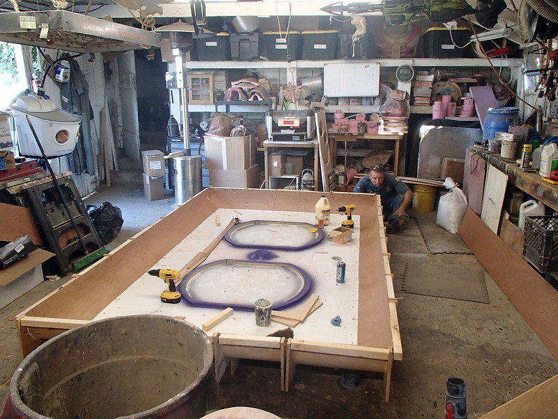
With the long sides done, I shifted to layering up the short sides:
Once the outside edges were completely laminated, I couldn't resist the urge to get a photo of me lying in the mold for scale:
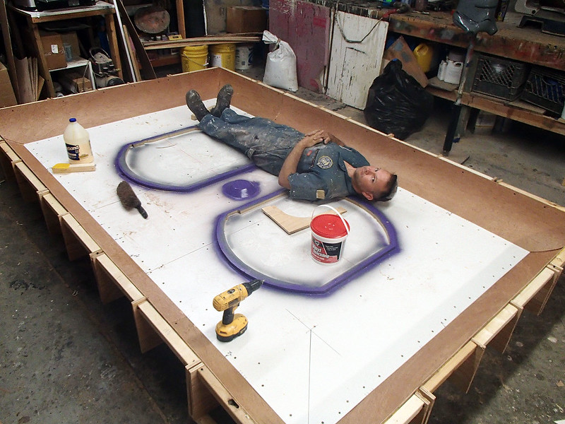
The next day began the process of smoothing out the mold. Since it was going to be a single-use disposable mold, I went the cheap route and did all of the fairing with lightweight household spackling paste:
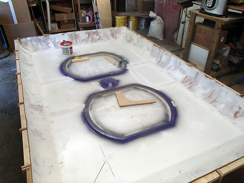
After a couple rounds of filling and sanding, I primed it and then went over any still-rough parts with some spot putty:
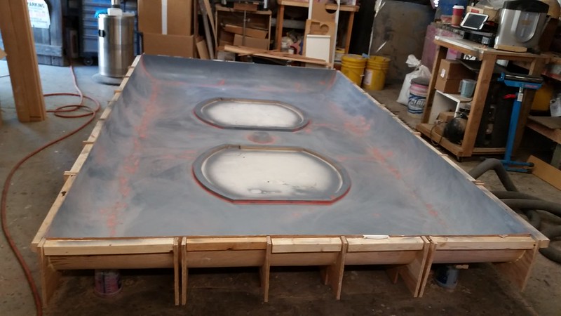
In order to make it slick and smooth for easy part removal, I gave the whole thing a couple of coats of gloss enamel. Since the part would be laid up with white gelcoat, I used black paint on the mold to provide better contrast:
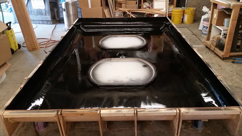
The next day, after the paint had dried, it was time to wax and buff the inside of the mold:
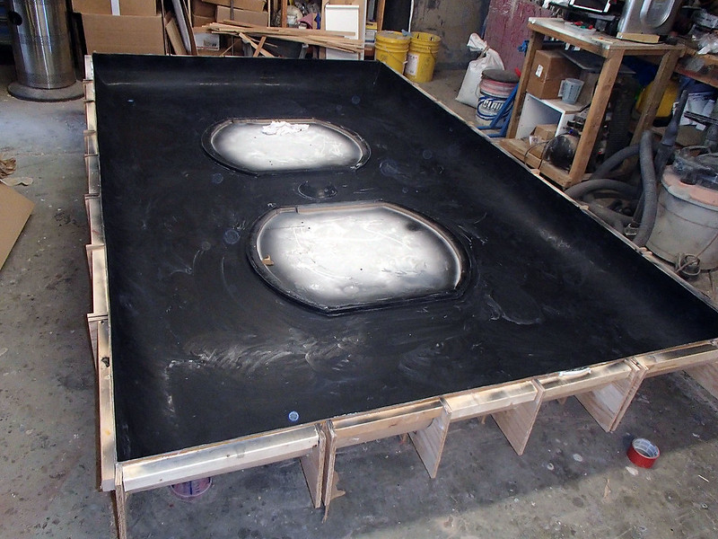
After applying a release agent, the whole thing got two coats of white gelcoat before it was time to start laying up the fiberglass. I started by building up the corners and the edges:
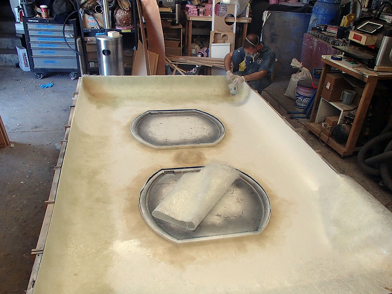
With the outside edges built up, we started building up the flat parts as well:
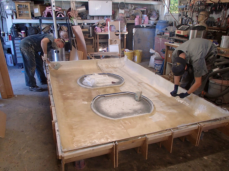
The end result was at least six layers of mat and cloth around the outside edge and at least four layers on the flat parts. Since I decided to make the screw hole in the middle a load bearing area, it got even more layers of glass:
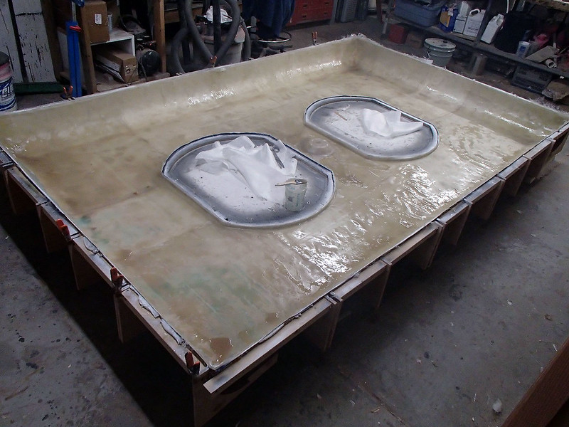
With the skin built up, the next chore was to add some wood battens to strengthen the entire structure. This began with simply buttering them up with resin and clamping them in place:
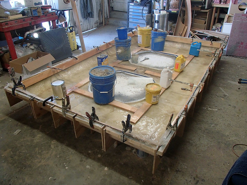
The next day, all of the wood was glassed over to trap it in place:
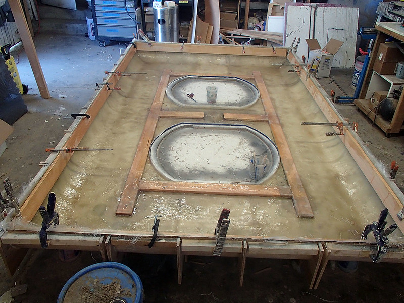
After allowing for plenty of cure time, the whole assembly was flipped over and the mold was dismantled:
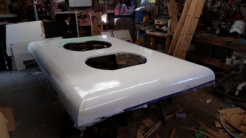
Success!
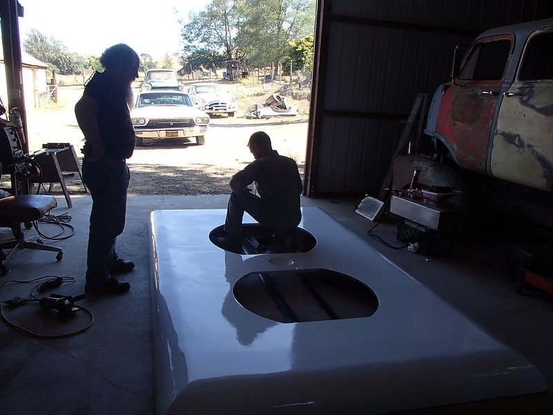
The mold was designed so that there would be some excess material to cut off around the edges after the part was laid up. In order to make a straight, flat edge, we moved the cover plate to the nice big, flat garage floor next door:
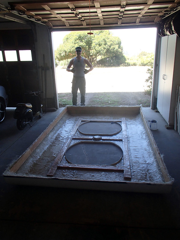
Then I used a custom precision height matching tool to mark a cutting line that was 6-3/8" off of the floor:
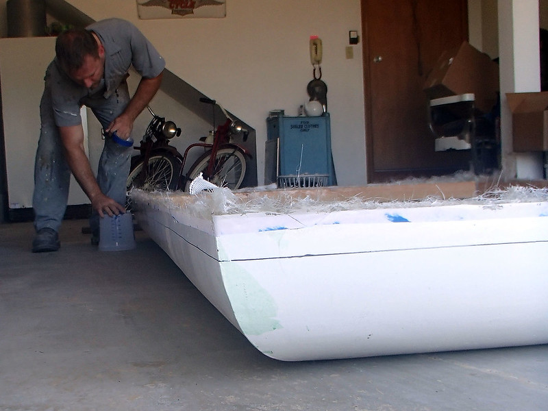
After moving the plate back to the shop, I broke out the circular saw and went to work:
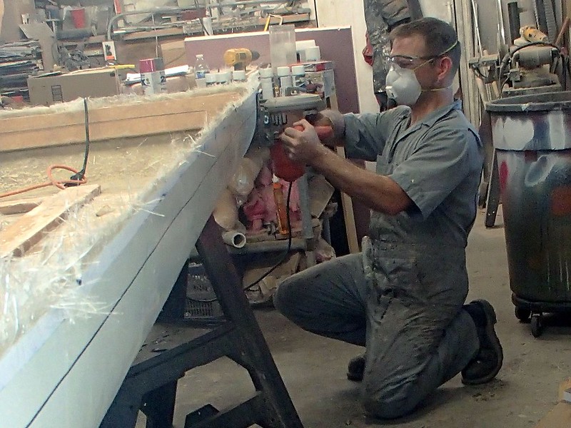
Here's the excess trimmed off:
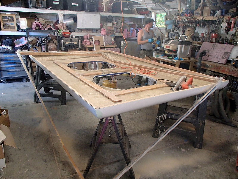
In order to seal off the exposed wood edge, I coated the edge with a mix of polyester resin and chopped strands of fiberglass:
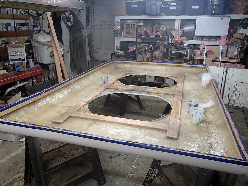
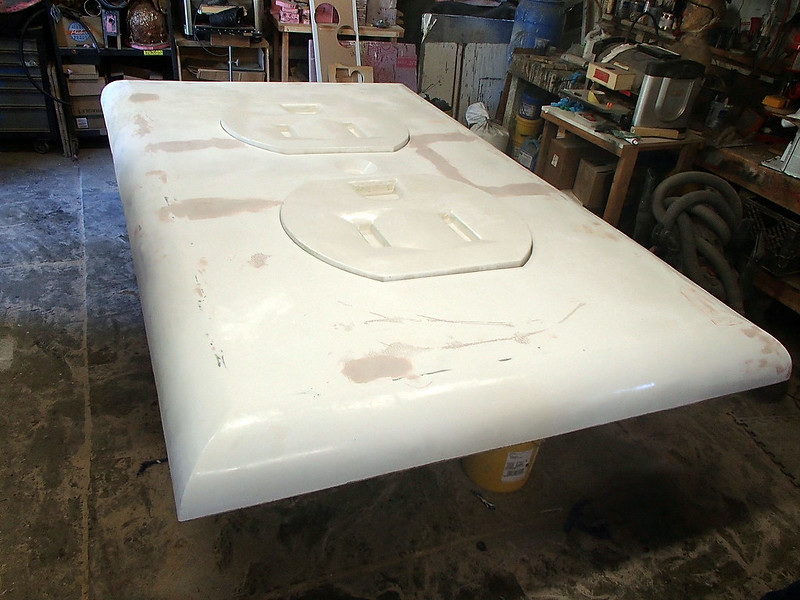
Once that cured, the whole thing was flipped over and we began the final bits of smoothing and filling. Since I was using a single-use mold, I didn't put anywhere near the kind of effort into smoothing it out that I normally would. Instead, all of the smoothing work was done on the final part. Most noticeable is the areas in the middle were there were seams in the melamine sheet on the flat sections;
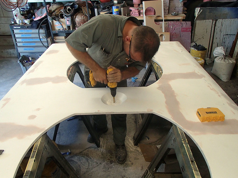
The last major operation for the cover plate was drilling the bolt hole that would hold it in place:
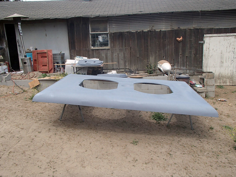
Then I sit it outside and gave the whole thing a coat of automotive primer:
The final paintjob was a two-stage automotive finish. Here's the whole thing with the color coat:
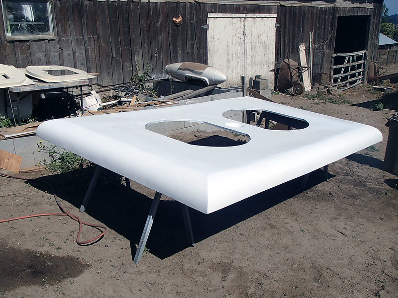
After this was dry, the whole thing got a couple of coats of gloss clear to make it shiny.
Meanwhile, work had begun on...
The Cord:
Since this particular build was going to end up on public display, the part that caused me the most concern was the cord. I wanted to make sure it was solid enough that it wouldn't be damaged if someone bumped into it.
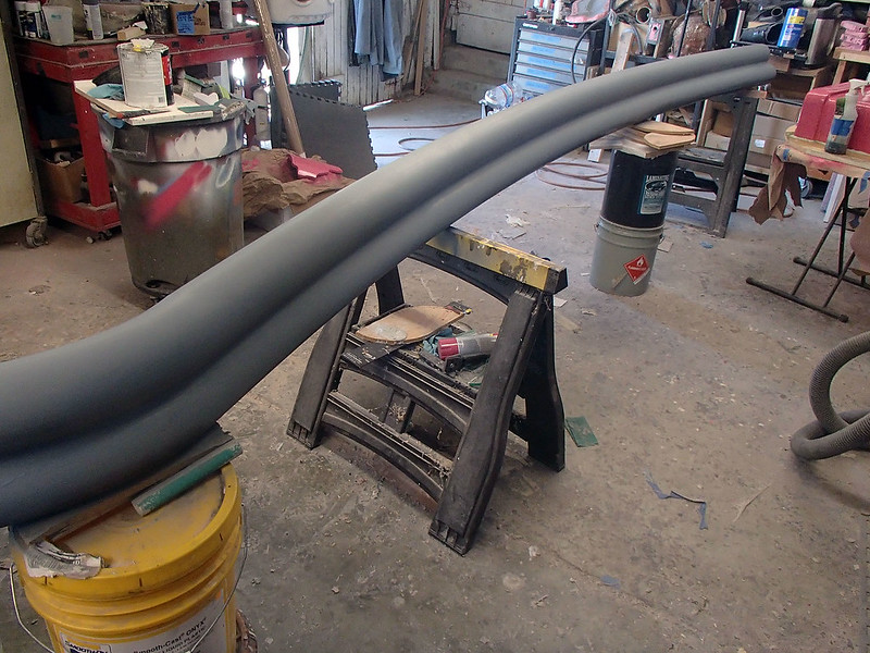
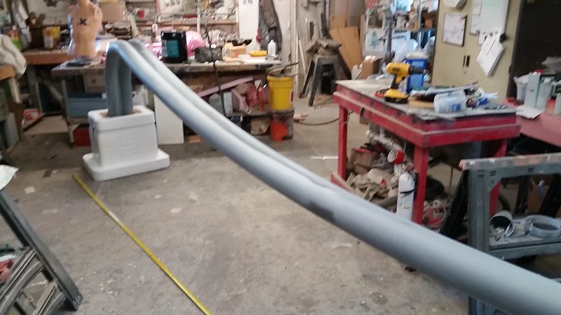
So I contacted my friend Ryan at Kertz Fabrication and had him weld me up a couple of lengths of 4-inch schedule 40 pipe that were bent into varying radii in order to simulate the sweep of the dangling cord. Here's the whole thing clamped up in his shop:
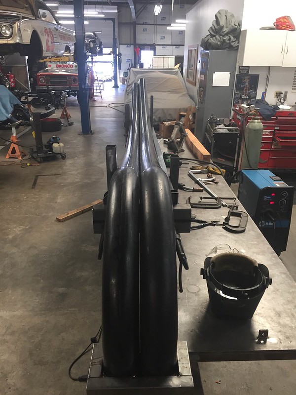
The two pipe runs were stitched together along their length. Then I went down to pick up the assembly and set it up in my shop:
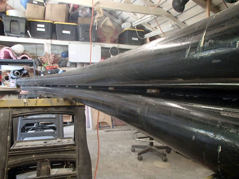
The seam was hidden under a fillet of bondo auto body filler:
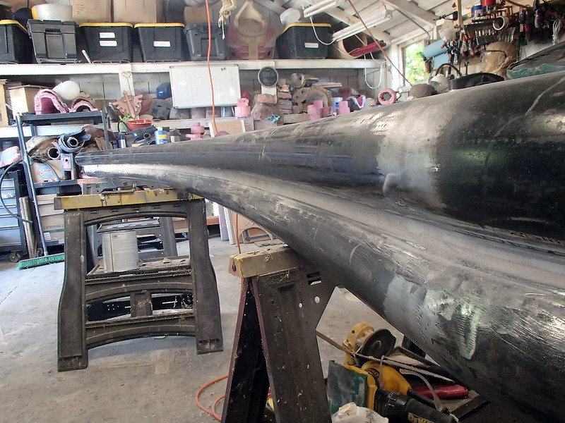
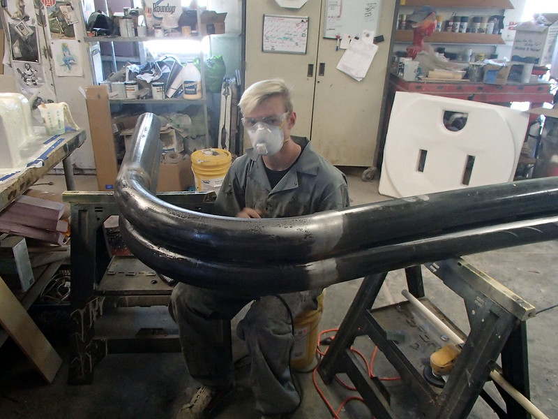
After I'd made the first pass with the filler, I tasked my assistant Loki with the last bits of filling and sanding to make it smooth:
Once it was all sorted out, the whole thing was primed:
To paint it, the assembly was stood on end to minimize contact points. Then it was give it's color coat and clear coat in an off-white in order to better distinguish it from the cover plate and the receptacles:
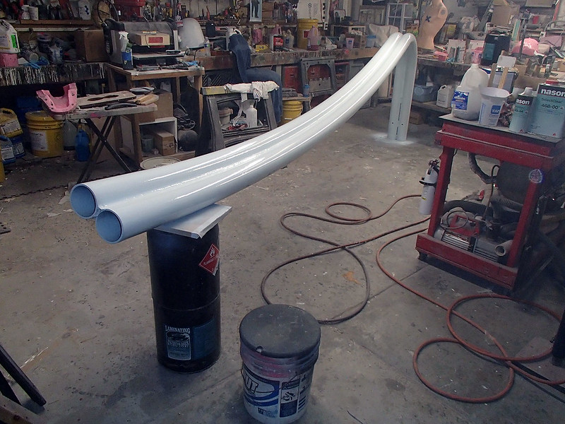
I forgot to mention that a one-foot length of 4-inch schedule 40 steel pipe weighs about ten pounds. So the whole assembly pictured above weighs in somewhere around 400 pounds. That was a lot of fun to move around. So I was glad to move on from the big heavy stuff in favor of working on...
The Plug:
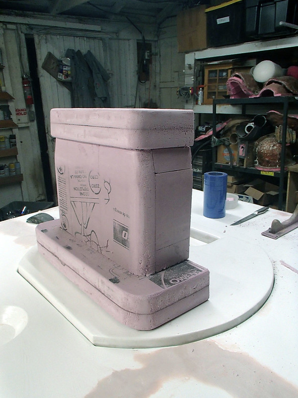
The plug was going to be symmetrical, so I could get away with making up a prototype for just half of it. Just like the receptacles, it started as a rough shape made of insulation foam:
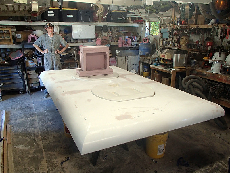
Here Loki is test-fitting it so I can be sure the proportions look right:
Since the foam will disintegrate in contact with most solvents, I had to skin over it with urethane resin:
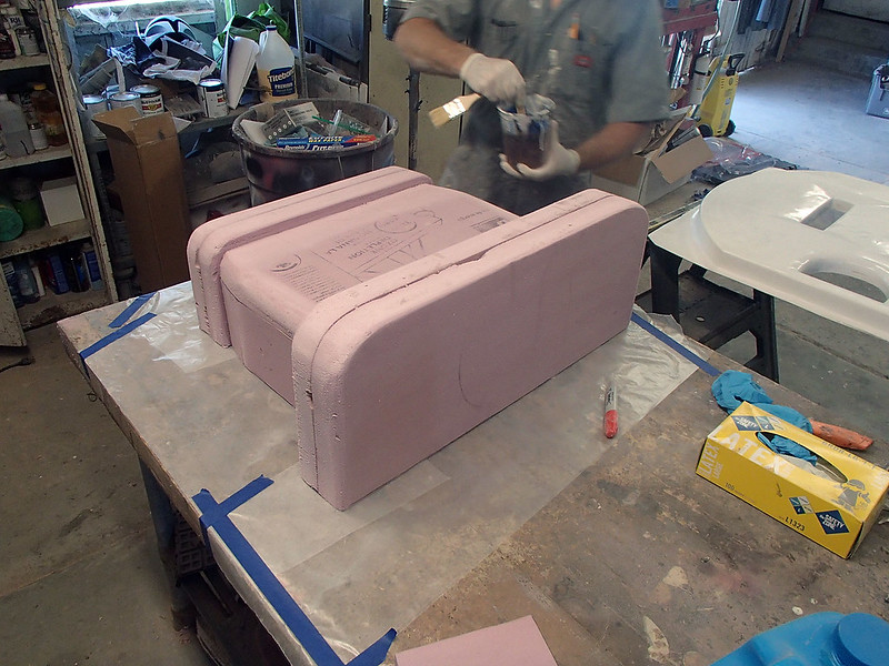
The resin would create a hard plastic shell that I could then fill and sand and paint:
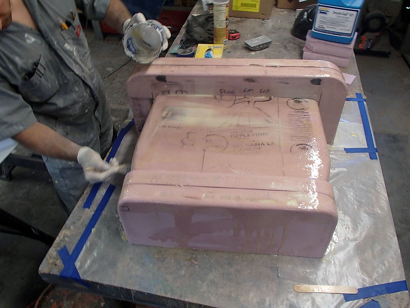
Once it cured, I set to work smoothing out the surface by adding body filler:
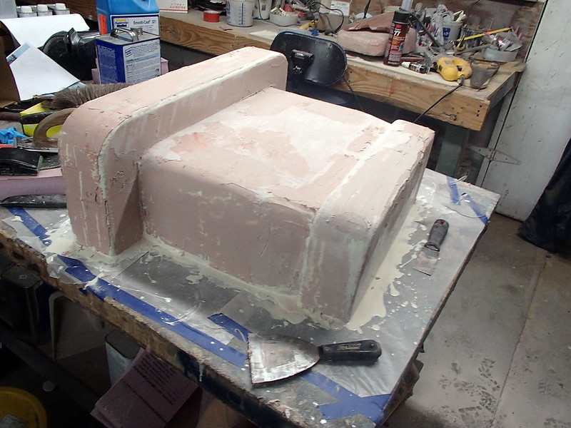
Here it is somewhere in the middle of fairing while Loki looks on from the background:
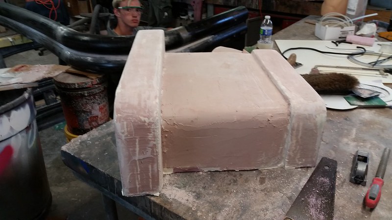
With most of the sanding and filling done, I started adding the small details:
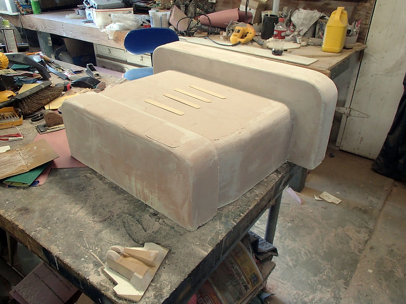
The last bit was smoothed out with spot putty:
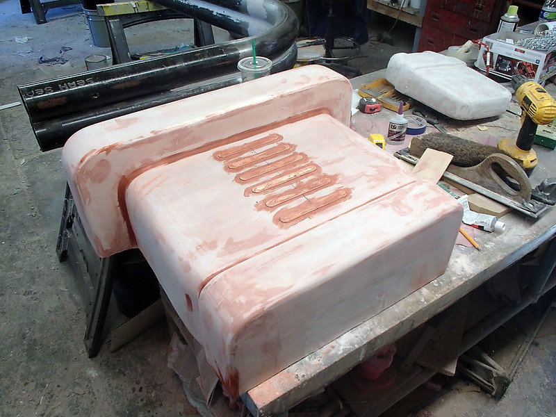
Then the whole thing got a coat of glossy lightish red paint:
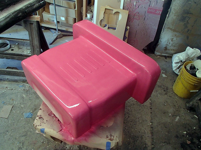
Then the PVA mold release:
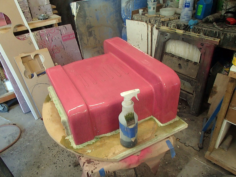
Gelcoat:
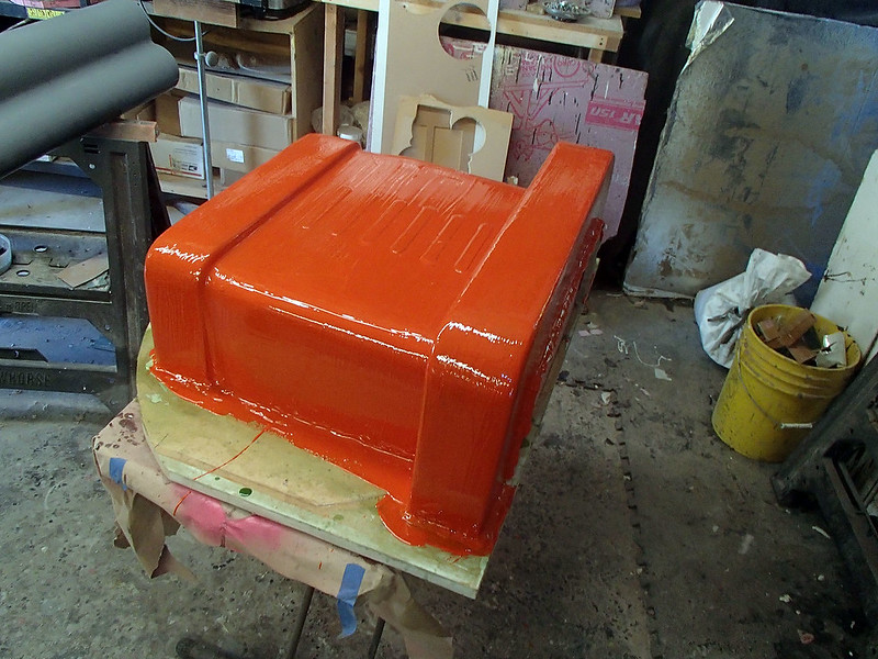
My friend Matt stopped by to help and laid up most of the fiberglass mold for that part:
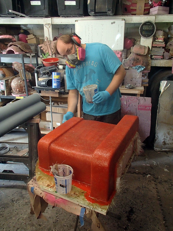
Once the mold was cured, I picked out the prototype, prepped the mold, and laid up the first fiberglass part:
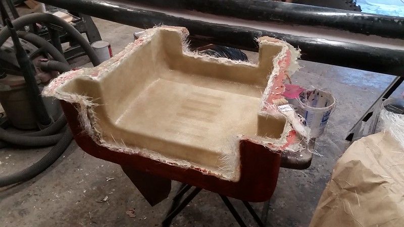
It came out pretty good:
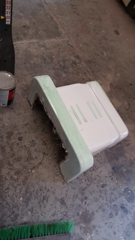
The green is the residual mold release film stuck to the part.
Here's the two halves test-fitted to one of the receptacles:
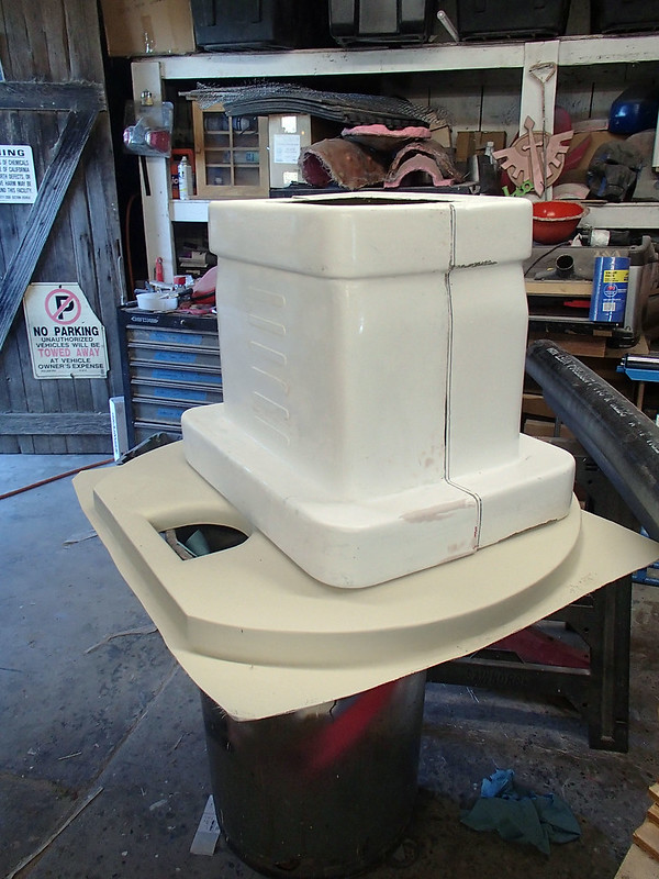
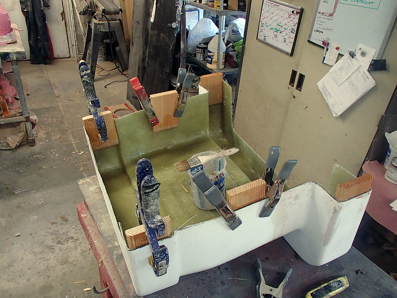
In order for them to lock together, I added a series of wooden tabs to the inside:
Here's the assembly dry-fitted to the cord:
Later it was all painted to match. That's about the same time as I started working on
The Screw Head:
This vital little detail was actually pretty straightforward. I started by making a digital model and splitting it in half so I could upload it to Lopez Dos Point Oh, my Carvewright CNC Machine.
Here's the parts once Lopez was done whittling them out of MDF stock:
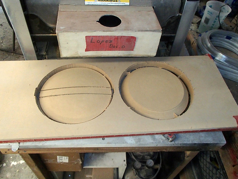
The initial test fitting revealed that I'd made it a hair too big:
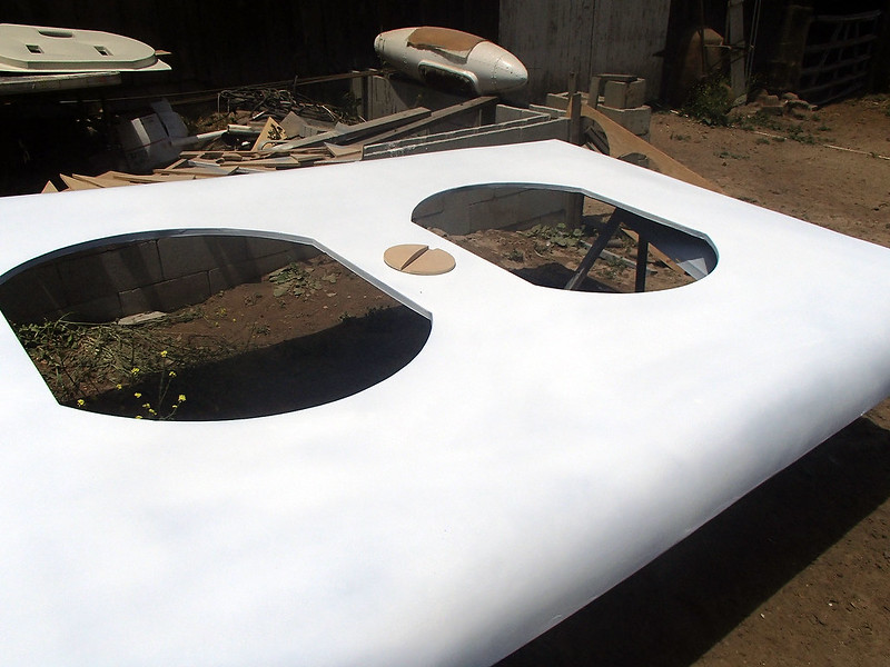
After shaving it down a bit on the belt sander, the whole thing was saturated in polyester resin to seal it against the elements:
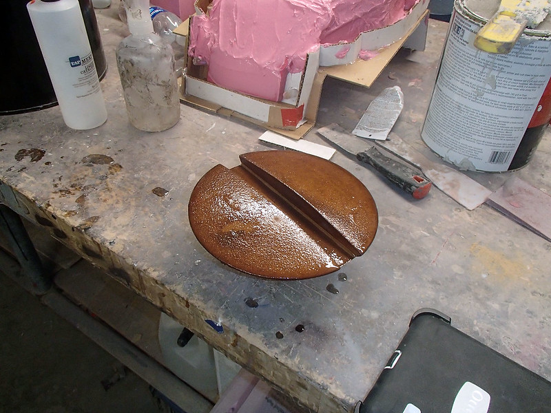
Later I sanded it smooth, primed it, and painted it to match the cover plate. With that done, all of the visible parts were made and it was time to shift focus to the structural piece.
The Bracket:
To hang the whole assembly on the wall, I designed a T-shaped bracket made of 3/16" thick steel angle stock. Since my welding is never really all that pretty, I hit up my father to stick the pieces together.
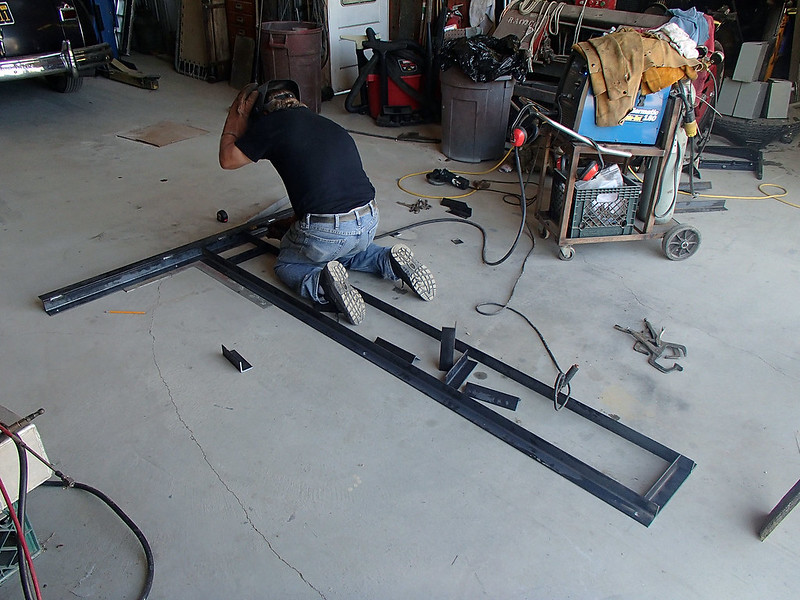
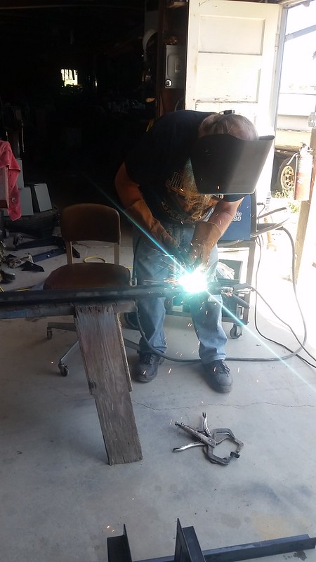
Once he'd done the hard part, we did a series of test-fitting to determine the just-right placement of the bracket that the steel "cord" would bolt onto:
Here's the end result:
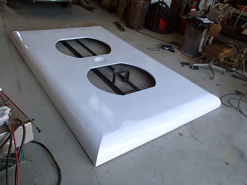
What you can't see is the part of the bracket centered in the middle of the cover plate to attach bolt through the screw hole.
In any case, everything was finally made.
Final Assembly:
To attach the receptacles to the cover plate, I set them in place and just laid up a bunch of fiberglass to tape them all together:
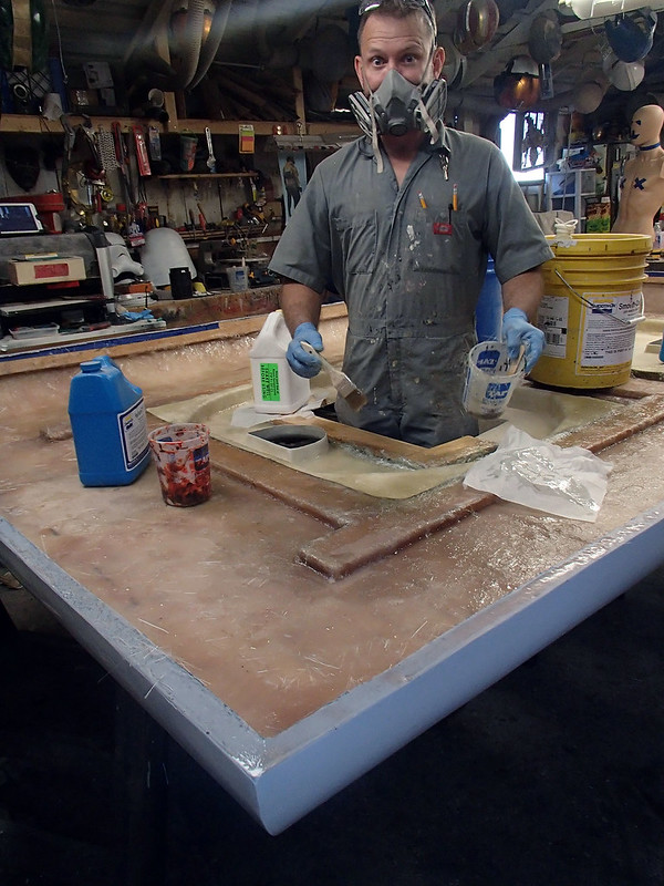
It worked out pretty well:
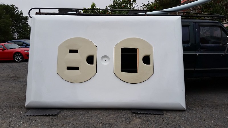
Then we loaded all of the parts onto a truck and took them downtown for...
Installation:
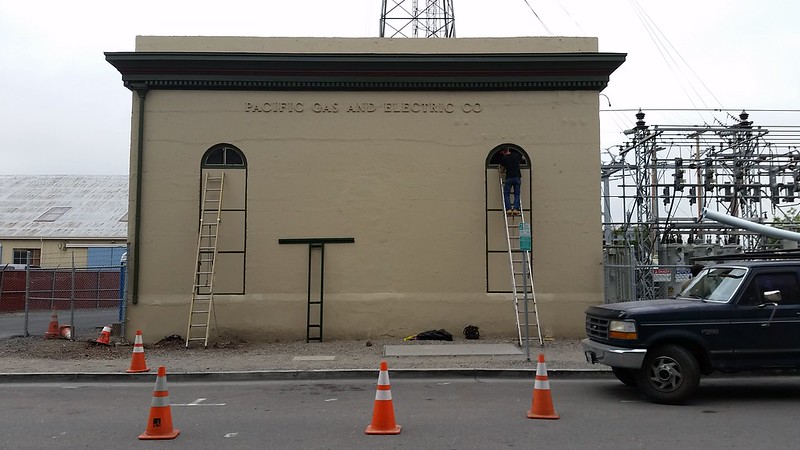
The folks at Pacific Gas & Electric (who own the building) were kind enough to have a crew with equipment standing by to assist with the install. Here's how it looked when we got there:
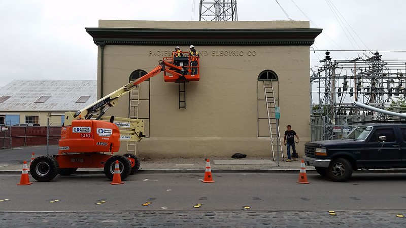
Since the building itself is nearly a century old, they insisted on having their own people do any drilling into the concrete walls. Here they are hanging the steel bracket in place:
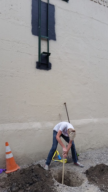
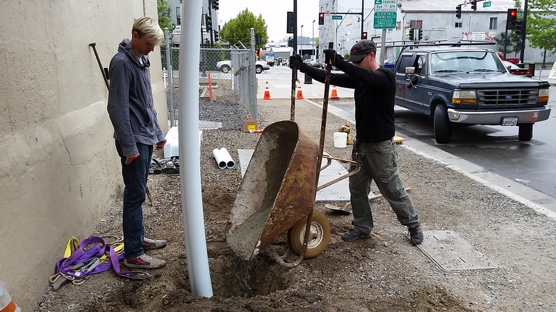
The bracket was mounted to the concrete with eight 1/2" concrete anchors set into epoxy. Then the areas of the wall that would be visible through the slots in the outlet were painted flat black. At this point, Loki and I dug a hole for the cord to set into:
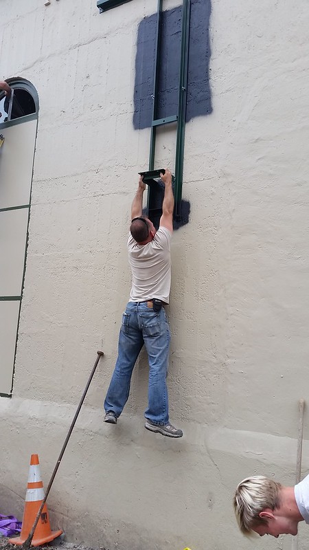
I also did a brief load test to make sure the bracket was structurally sound:
That done, the coverplate was lifted into place and hooked onto the bracket:
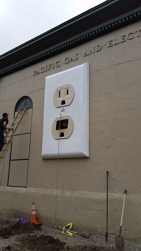
With the lifting eye removed from the screw hole, the plate was bolted into place and the cosmetic screw head was glued in. Then the cord was craned into position and bolted onto the steel bracket:
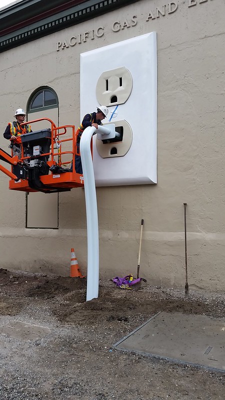
Once everything was in place, Loki and Trevor poured some 240 pounds of concrete into the hole:
While they were doing that, I got into the JLG basket and assembled the plug around the cord:
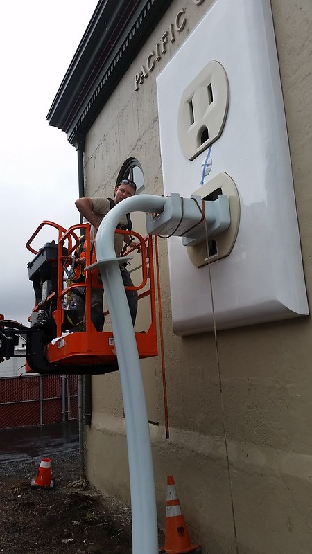
The bottom half was bolted to the switchplate and the top half was epoxied into place on top of it:
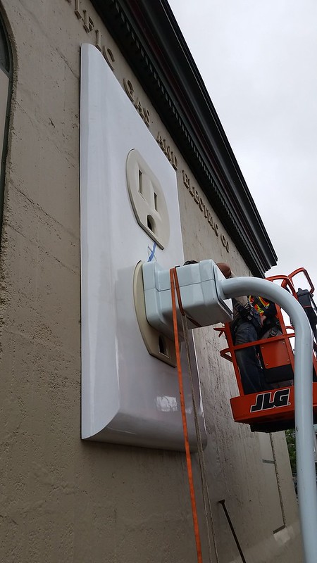
Here I am applying a strap to hold the two halves together while the epoxy cured:
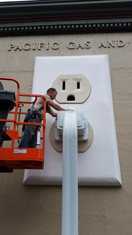
And that's a done thing:

Here's a couple of passers-by to provide a better sense of scale:
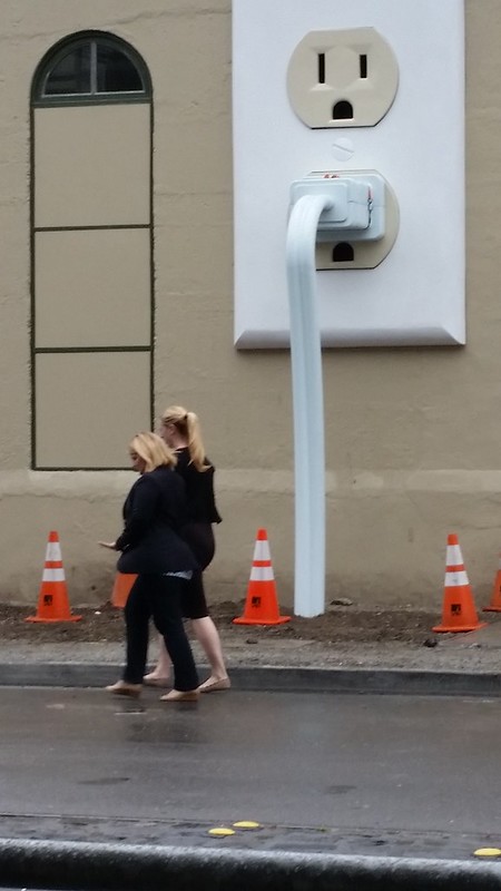
And a view from across the street:
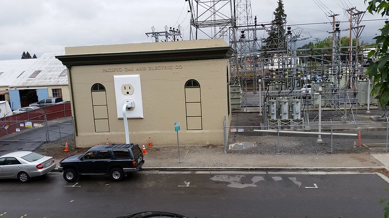
Directly across the street there's a four-story parking lot, so I had to make it a point to get more of a bird's-eye view:
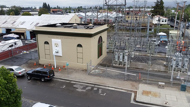
Here's what it looks like from the fourth floor across the street:
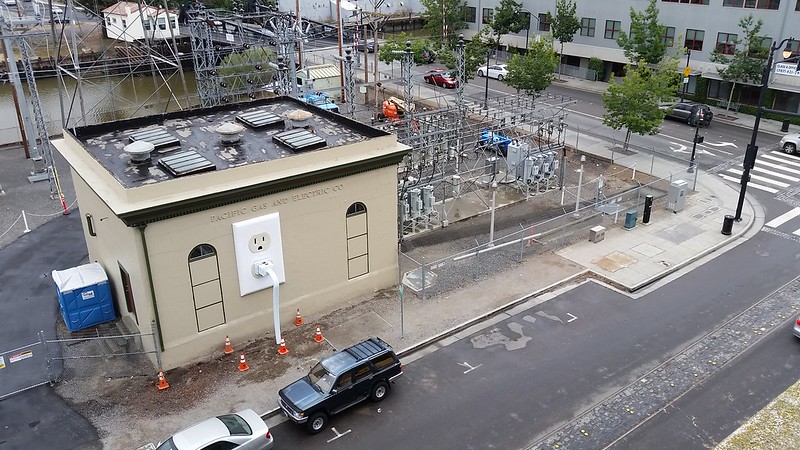
So if you find yourself in downtown Petaluma, be sure to head over to the corner of 1st and D Street to check this thing out.
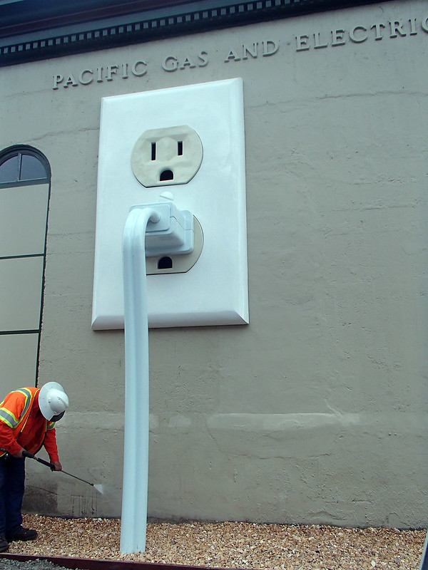
And that completes the construction of the tallest thing I've built so far. Stay tuned for further updates and be sure to like Basal Ganglia Studios on Facebook for more information about them.
.
Is it rude to point out that receptacles would be more safe if the ground hole is placed at the top of the plug?
ReplyDeletehttps://www.mikeholt.com/technical.php?id=grounding/unformatted/9-23-99&type=u&title=Receptacles%20-%20Ground%20Up%20or%20Ground%20Down?%20(9-23-99)
If you're going to point that out, you should also point out that being outdoors means it should really be a GFCI outlet and using an ungrounded cord is likely to be dangerous as well.
DeletePretty cool! Out of curiosity, what would a receptacle or two cost?
ReplyDeleteIf there's something you'd like me to make for you, shoot me an email at sthorsson99@yahoo.com and we can discuss it.
DeleteAwesome. Thank you for the details. Love it.
ReplyDeleteAs someone who has bought many replacement switches, outlets and cover plates, I cracked up when I saw your outlet was ivory and the plate was white. That's how mine always end up too. Ha! Great job!!!
ReplyDelete